What's inside
As an Amazon Associate I earn from qualifying purchases. This post may contain affiliate links at no extra cost to you.
MIG Welding Aluminum Settings: Voltage, Wire Speed, and Setup
For most aluminum MIG jobs, start with a clean 100% argon supply, DCEP polarity (electrode positive), a push technique, and the voltage and wire-speed range recommended for your wire diameter and metal thickness—then fine-tune on scrap of the same alloy and thickness. The settings below are practical starting points, not universal prescriptions: machine calibration, joint fit, alloy, and travel speed all affect the result.
Starting settings by thickness and wire diameter
Use these ranges as a first pass with a conventional constant-voltage MIG welder. They assume 4043 or 5356 aluminum wire, flat or horizontal welding, a short stickout, and material that has been cleaned immediately before welding. Check your machine’s chart as well; its numbers may differ because of its output characteristics.
As an Amazon Associate we earn from qualifying purchases at no extra cost to you.

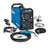

| Aluminum thickness | Wire diameter | Starting voltage | Starting wire speed | Practical note |
|---|---|---|---|---|
| 0.8–1.2 mm (0.032–0.047 in) | 0.8 mm (0.030 in) | 15–17 V | 180–280 in/min | Use a spool gun or push-pull system; tack frequently to limit burn-through. |
| 1.5–2.0 mm (0.060–0.080 in) | 0.8 mm (0.030 in) | 17–19 V | 250–380 in/min | A close-fitting joint and steady travel help prevent a cold start or a hole. |
| 2.0–3.2 mm (0.080–0.125 in) | 0.9 mm (0.035 in) | 19–22 V | 300–450 in/min | A common general-purpose range; make a test bead before welding the part. |
| 3.2–6.4 mm (0.125–0.250 in) | 1.0 mm (0.040 in) | 21–25 V | 350–550 in/min | Prepare thicker joints with a bevel or root gap as needed; consider preheat for large heat sinks. |
| 6.4 mm (0.250 in) and thicker | 1.2 mm (0.047 in) | 24–29 V | 450–700 in/min | Often needs multiple passes, higher-capacity equipment, and a qualified procedure for critical work. |
Wire speed is closely tied to amperage on a conventional MIG machine: increasing it generally raises current and deposition. Voltage mainly changes arc length and bead profile. If the wire repeatedly stubs into the work, increase voltage slightly or reduce wire speed. If the arc is harsh and the bead is wide or undercut, try reducing voltage or wire speed in small increments. Change one control at a time so you can tell what helped.
Set up the welder before striking an arc
-
Choose wire and polarity for the job
Use aluminum filler wire compatible with the base alloy and service requirements. 4043 is commonly selected for many 6xxx-series applications and tends to flow readily; 5356 is often chosen when higher strength or anodized color matching matters, subject to alloy and application limits. For standard solid aluminum MIG wire, set DCEP: the gun is positive and the work clamp is negative. This is the usual mig welding aluminium polarity. Confirm the machine’s terminal connections rather than relying on cable color.
-
Use the right gas and flow
Use 100% argon for most aluminum MIG work. A starting flow rate is about 20–30 cubic feet per hour (9–14 L/min), adjusted for nozzle size, drafts, and setup. Too little flow can leave porosity; excessive flow can create turbulence that draws air into the shielding. Keep the work out of drafts and check for leaks. Helium-argon blends can help with thick sections, but they require suitable equipment and procedure adjustments.
-
Make the wire path low-friction
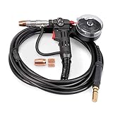
Aluminum wire is soft, so a long conventional steel-wire liner can cause buckling and bird-nesting. A spool gun places the wire spool close to the contact tip; a push-pull gun uses coordinated drive rolls to feed from a larger spool. Use U-groove drive rolls, the correct roll pressure, an aluminum-compatible liner, and a contact tip sized for the wire. Set pressure only high enough to feed reliably without deforming the wire.
-
Clean, fit, and test
Remove oil and dirt with a suitable solvent, then remove oxide with a dedicated stainless-steel brush used only on aluminum. Clean just before welding; oxide reforms quickly. Clamp securely, check joint fit, and run a bead on a matching scrap piece. Aluminum conducts heat away quickly, so a start can be cold while the end becomes too hot. Keep moving steadily and avoid lingering at the end.
How to tune the bead without chasing settings
Start near the middle of the table’s range and weld a short test bead. Listen for a consistent arc and inspect both the face and, when possible, the back of the joint. A narrow, rope-like bead with poor tie-in usually indicates insufficient heat, excessive travel speed, or a dirty joint. A puddle that suddenly collapses through thin sheet suggests too much heat or too slow a travel pace. Adjust voltage or wire speed by a small amount, then repeat on fresh scrap.
Use a push angle of roughly 10–15 degrees rather than dragging the gun. Keep stickout consistent and follow the machine or gun maker’s guidance for contact-tip-to-work distance. A larger weave is not a substitute for correct heat and travel; on thin sheet, a controlled straight bead and spaced tacks are often easier to manage.
Spool-gun and wire-feed troubleshooting
| Symptom | Likely cause | Adjustment to try |
|---|---|---|
| Bird-nesting at the drive rolls | Wire snag, excessive roll pressure, or resistance in the liner or tip | Stop and cut back damaged wire; inspect the path, reduce pressure, and replace worn or mismatched consumables. |
| Wire slips or feeds unevenly | Pressure too low, dirty rolls, or a kinked gun cable | Clean the rolls, straighten the cable, and increase pressure only enough to feed consistently. |
| Wire burns back to the tip | Wire speed too low for voltage, long pauses, or incorrect tip fit | Increase wire speed slightly, check the tip size, and keep travel moving. |
| Porosity or a sooty-looking bead | Contamination, drafts, leaks, or poor gas coverage | Reclean the joint, check gas flow and connections, and shield the work from airflow. |
With a spool gun, keep the gun cable as straight as practical and avoid sharp bends. The short wire path reduces feeding problems, but the gun’s added weight can make a steady travel angle harder to maintain. Inspect the contact tip and nozzle regularly: aluminum spatter and wire buildup can interfere with feeding and gas coverage. Replace worn tips rather than compensating with drive-roll pressure.
Pulse MIG and cast aluminum: important limits
Pulse MIG welding aluminum alternates between higher-current pulses that transfer droplets and a lower background current that maintains the arc. It can improve control and reduce heat input in some situations, particularly with thin material or out-of-position work, but results depend on a compatible pulsed power source, wire-feed system, and synergic program. Pulse MIG welding settings are not interchangeable with the conventional voltage and wire-speed ranges above. Select the machine’s aluminum program for the wire diameter and alloy, enter material thickness if supported, and verify the result on a test coupon.
Cast aluminum is less predictable than clean, wrought sheet or plate. Porosity, oil, oxide, and unknown alloy composition can cause cracks or contamination even when the arc settings seem right. Remove coatings and contamination thoroughly, and use filler chosen for the casting and intended service. A modest preheat may help with a thick casting, but overheating can damage the part or release trapped contaminants. For structural, pressure-containing, or safety-critical castings, have a qualified welding professional assess whether repair is appropriate.
Good aluminium MIG welding settings are only part of the result: correct polarity, clean material, stable feeding, and consistent technique matter just as much. Keep a brief record of the wire, thickness, gas flow, voltage, wire speed, and travel approach that worked on each material; that gives you a more useful starting point next time than a single “best” setting.